 |
||
| Design Optimization Expert System | ||

|
||
 |
||
|
|
||
| Free |
 |
Free |
|
ANSYS Workbench Model Optimization Part 1: Model Background Download the complete Case Study here (PDF) |
|
|
This case study demonstrates some of the benefits of using DOES to optimize
an ANSYS model including:
The ANSYS ōFlexible Spring Mountö model is shown here:
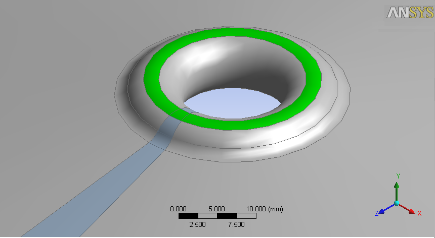
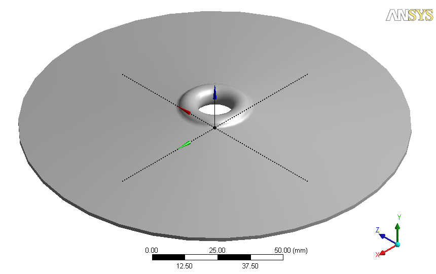 The model was created and manually optimized for several days by a customerÆs senior engineer before it was given to OPTIMUM Power Technology. The solid model of the mount was created using the Design Modeler from ANSYS, Inc. The goal of the optimization was to achieve the most deflection of the mount in the ¢ Y direction while staying within the allowable yield strength of the material. In order to perform a good optimization, it is essential to start with a high quality parametric model that can be fully optimized without compromising the partÆs original design intent. The following sketch shows the actual parameters assigned to the mount. 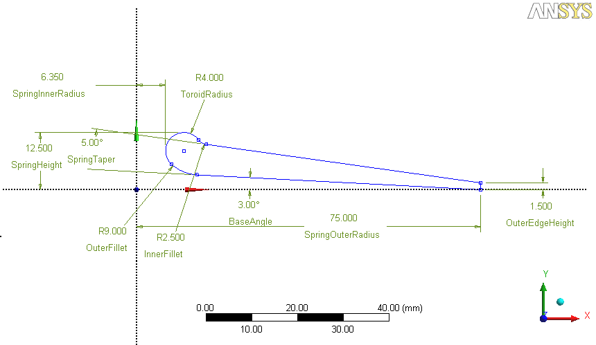 Analysis of the Manually Optimized Flexible Spring Mount Before any downstream optimization is performed it is essential to analyze the manually optimized part. For this spring mount it was determined that symmetry could be used to significantly reduce the time required to perform the analysis of the part. Using the Design Modeler from ANSYS it is possible to segment the model, as shown below, without modifying the original CAD model. As such, a 10-degree segment of the mount was created to perform the analysis. |
|
|
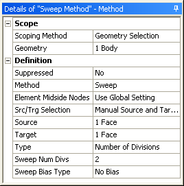
In this analysis, we set up parameters that reflected the original design intent of the model with a load of 9000
pounds or 40034 Newtons. A force of 1112.055 Newtons represents the load on a 10-degree segment of the mount. This
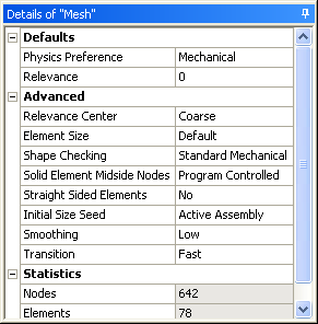
load was applied to the segment. Once constraints and loads were applied to the segment, meshing and analysis settings were defined in the ANSYS Mechanical product. The ōSweep Methodö and ōMeshö settings that were used are shown in the two dialog boxes below. |
|
|
|
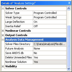
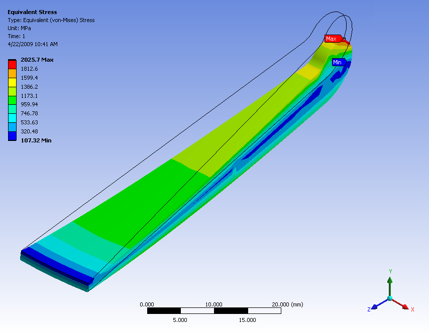
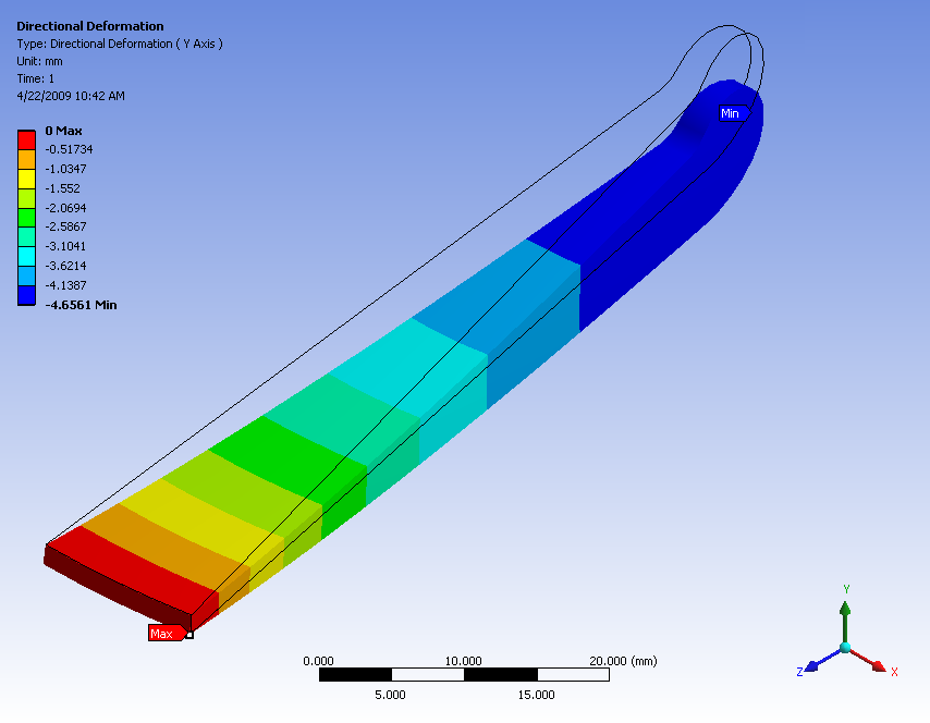
The ōAnalysis Settingsö were specified to allow for non-linear large deflection analysis. With these settings, loads and boundary conditions, the analysis of the manually optimized model showed an equivalent maximum stress of 2025.7 MPa and a deflection of -4.6561 mm. The resulting displays of the analysis results are shown below. Note that the rigidity of the manually optimized mount causes the maximum stress to occur at the point of loading. |
|
|
|
Stress Results. The black outline denotes the unloaded model. |
Displacement Results. The black outline denotes the unloaded model. |
|
|
Page 2: Optimization of Model Using DOES -> |
|